Description
| eClass-No.: | 37010301 |
| Application: | Oil and gas processing, refineries, petrochemicals, chemicals, power plants, district heating, solar thermal power stations, pulp and paper, steelworks, sugar processing, industrial and plant manufacturing, Shipbuilding, specific applications in HVAC |
| Medium: | Refrigerant, cooling water, warm water, hot water, thermal oil, steam, gas, alkalis, acids, de-ionised water, pure steam, etc. |
Features
• Carbon steel / stainless steel body
• Double offset construction: Rotary movement (90°) without wear or friction
• Metallic or PTFE+C sealing
• Bi-directional tightness
• Replaceable seat ring
• Fire Safe acc. to ISO 10497 / BS6755
• ATEX (optional)
Technical data
Double flanged high performance valve (Cast steel, Stainless steel)

| Figure | Nominal pressure | Material | Nominal diameter | Sealing element |
| 31.1221) | PN 6 – PN 10 | 1.0619+QT | DN 200-800 | PTFE+C (TS) |
| DN 200-1200 | Stainless steel (CS) | |||
| 32.1221) | PN16 | 1.0619+QT | DN 200-800 | PTFE+C (TS) |
| DN 200-1200 | Stainless steel (CS) | |||
| 34.1221) | PN 25 | 1.0619+QT | DN 200-800 | PTFE+C (TS) |
| DN 200-1200 | Stainless steel (CS) | |||
| 51.1221) | PN 6 – PN 10 | 1.4408 | DN 200-800 | PTFE+C (TS) |
| DN 200-1200 | Stainless steel (CS) | |||
| 52.1221) | PN16 | 1.4408 | DN 200-800 | PTFE+C (TS) |
| DN 200-1200 | Stainless steel (CS) | |||
| 54.1221) | PN 25 | 1.4408 | DN 200-800 | PTFE+C (TS) |
| DN 200-1200 | Stainless steel (CS) | |||
| Face-to-face dimension series 14 acc. to EN 558-1 Standard: Bolted Bottom Cover (BBC)
Optional: Welded Bottom Cover (WBC) |
||||
| PN100* | 1.4581/1.4571 | DN15- 25 | -10°C to +300°C
(up to +400°C on request) |
Flange DIN EN 1092-1 | |||
| * optional flange ANSI600 EN 1759-1 | |||||||
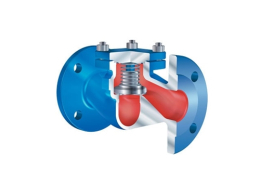
| Construction | |||||||
| Safety valve, spring loaded, direct loaded | |||||||
| Requirement | |||||||
| Acc. to EN ISO 4126-1, VdTÜV-leaflet 100, AD2000-A2 | |||||||
| Type-test approval | |||||||
| Standard safety valve: | Fig. 961/962/963 | TÜV · SV · . . -1041 · D/G | |||||
| Standard safety valve: | Fig. 961/963 | TÜV · SV · . . -1041 · F | |||||
| Sizing | |||||||
| for steam, air and water refer to capacity tables, calculations acc. to EN ISO 4126-1, TRD 421 and AD2000-A2 | |||||||
| Details required | |||||||
| Medium gasform: | Mass flow (kg/h), molar mass (kg/kmol), Isotropic exponent, temperature (°C), set pressure (barg), back pressure (barg) | ||||||
| Medium liquid: | Mass flow (kg/h), density (kg/m3), viscosity, temperature (°C), set pressure (barg), back pressure (barg) | ||||||
| Order data: | |||||||
| ARI-SAFE-TCP – Safety valve, Figure ….., DN … / …, PN .. / .., Material …….., Set pressure …. bar | |||||||
| standard: without metal bellows | |||||||
| Superimposed back pressure | no backpressure allowed | ||||||
| Built up back pressure | max. 10% from set pressure (higher on request) | ||||||
| Parts | ||||
| Pos. | Sp.p. | Description | Fig. 67.961/962/963 | Fig. 57.961/963 |
| 1 | Body | GX5CrNiMoN19-11-2, 1.4581 | ||
| 4 | Spindle guide | X6CrNiMoTi17-12-2, 1.4571 | ||
| 7 | x | Gasket | Pure graphite (CrNi laminated with graphite) | |
| 11 | Bonnet, closed | EN-GJS-400-18U-LT, EN-JS1049 | GX5CrNiMoN19-11-2, 1.4581 | |
| 12 | Disc | X6CrNiMoTi17-12-2, 1.4571 | ||
| 14 | x | Spindle | X6CrNiMoTi17-12-2, 1.4571 | |
| 17 | Adjusting screw | X2CrNiMo17-12-2, 1.4404 | ||
| 27 | x | O-ring | FPM | |
| 28 | Cap, closed | GX5CrNiMoN19-11-2, 1.4581 | ||
| 29 | Cap, open | GX5CrNiMoN19-11-2, 1.4581 | ||
| 30 | Cap, gastight | EN-GJS-400-18U-LT, EN-JS1049 | GX5CrNiMoN19-11-2, 1.4581 | |
| 36 | Lever, closed
(optional: Fig. … .961 / Fig. … .962) |
EN AC-4420 (Al) | ||
| 37 | x | Spring | FDSiCr | X10CrNi18-8, 1.4310 |
| 65 | Coupling | X6CrNiMoTi17-12-2, 1.4571 | ||
| 66 | O-ring | FPM | ||
| 67 | Lift button | X6CrNiMoTi17-12-2, 1.4571 | ||
| └ Spare parts | ||||
| DN | 15 | 20 | 25 |
| Spring ranges: Standard design | ||
| (barg) | 0,2 – 0,25 | |
| (barg) | > 0,25 – 0,5 | |
| (barg) | > 0,5 – 1 | |
| (barg) | > 1 – 1,4 | |
| (barg) | > 1,4 – 2,95 | |
| (barg) | > 2,95 – 4,9 | |
| (barg) | > 4,9 – 12 | |
| (barg) | > 12 – 20 | |
| (barg) | > 20 – 27 | |
| (barg) | > 27 – 35 | |
| (barg) | > 35 – 45 | |
| (barg) | > 45 – 59 | |
| (barg) | > 59 – 100 | |
Information / restriction of technical rules need to be observed!
The engineer, designing a system or a plant, is responsible for the selection of the correct valve.
Resistance and fitness must be verified (contact manufacturer for information, refer to Product overview and Resistance list).
| DN | 15 | 20 | 25 | ||||
| NPS | 1/2 x 1/2 | 1/2 x 3/4 | 3/4 x 1/2 | 3/4 x 3/4 | 3/4 x 1 | 1 x 1 | |
| DN1 / DN2 | DN 15 / 15 | DN 15 / 20 | DN15 / 25 | DN 20 / 20 | DN 20 / 25 | DN 25 / 25 | |
| Dimensions | ||||||||
| d0 | (mm) | 12 | 12 | 12 | 12 | 12 | 12 | 12 |
| A0 | (mm2) | 113 | 113 | 113 | 113 | 113 | 113 | 113 |
| GE | (inch) | 1/2 | 1/2 | — | 3/4 | 3/4 | 3/4 | 1 |
| GA | (inch) | 1/2 | 3/4 | — | 1/2 | 3/4 | 1 | 1 |
| b | (mm) | 15 | 15 | — | 16 | 16 | 16 | 18 |
| l | (mm) | 42 | 47 | — | 42 | 47 | 50 | 50 |
| l1 | (mm) | 34 | 34 | — | 34 | 34 | 34 | 34 |
| l2 | (mm) | 110 | 110 | 110 | — | 110 | 110 | 110 |
| l3 | (mm) | 85 | 85 | 85 | — | 85 | 85 | 120 |
| H | (mm) | 189 | 189 | 110 | 189 | 189 | 189 | 189 |
| X | (mm) | 100 | 100 | 85 | 100 | 100 | 100 | 100 |
| Weights | ||||||||
| standard | (kg) | 1,2 | 1,2 | — | 1,2 | 1,2 | 1,2 | 1,2 |
| optional: flange design | (kg) | 3,7 | 4,5 | 5,0 | — | 5,4 | 5,9 | 6,6 |
| DN | 15 | 20 | 25 | |
| Flange acc. to DIN EN 1092-1 | ||||
| ØD | (mm) | 105 | 130 | 140 |
| b | (mm) | 20 | 22 | 24 |
| Standard-Flangeholes | ||||
| ØK | (mm) | 75 | 90 | 100 |
| n x Ød | (mm) | 4×14 | 4×18 | 4×18 |
| Pressure-temperature-ratings | Intermediate values for max. permissible operational pressures can be determined by linear interpolation of the given temperature / pressure chart. |
| acc. to DIN EN 1092-1 | -60°C to <-10°C | -10°C to 100°C | 150°C | 200°C | 250°C | 300°C | 350°C | 400°C | 450°C | ||
| 1.4581 | PN100 | (bar) | 75 | 100 | 98 | 93,3 | 88,5 | 83,3 | 80,4 | 78 | — |
| Certified coefficient of discharge Kdr (Values for D/G variable: < 4 bar) | |||
| DN | 15 | 20 | 25 |
| TÜV · SV · . . – 1041 · D/G | 0,30 | ||
| TÜV · SV · . . – 1041 · F | 0,23 | ||
| Parts | ||||
| Pos. | Sp.p. | Description | Fig. 34.122 | Fig. 54.122 |
| 1 | Body | 1.0619+QT | 1.4408 | |
| 2 | Disc | 1.4408 (optional 1.4460) | ||
| 3 | Pivot | 1.4021+QT | 1.4542 | |
| 4 | Bottom cover | 1.4404 (BBC), (optional WBC: 1.0565) | 1.4404 | |
| 5 | Stem | 1.4021+QT | 1.4542 | |
| 6 | Pin | A4-70 | ||
| 7 | Bushing P1 | Inconel 625 | ||
| 8 | Sicherungsring | PTFE on stainless steel net | ||
| 9 / 24 | x | Shim 3) | 978-C / SIGRAFLEX HIGH PRESSURE (SIGRAFLEX HIGH PRESSURE for steam version) | |
| 10 | x | Sitzring | CS: 1.4404 (optional: 1.4539) TS: PTFE+C; special material on request |
|
| 11 | Retaining ring 1.0425 | 1.4404 | ||
| 12 | Socket screw | A4-80 | ||
| 13 | Washer | A4 | ||
| 14 | Back-up-ring | 1.4404 | ||
| 15 | x | Box packing | Graphite | |
| 16 | Shaft seal bushing | 1.4404 | ||
| 17 / 18 | x | O-ring | EPDM (not fitted in steam version) | |
| 19 | Gland | 1.4404 | ||
| 20 | Hexagonal screw | A4-70 | ||
| 21 | Key | A4 | ||
| 22 | Axial-washer | P1 | Inconel 625 | |
| 23 | Shim | 978-C / SIGRAFLEX HIGH PRESSURE (SIGRAFLEX HIGH PRESSURE for steam version) | ||
| 26 | Hexagon | screw A4-70 | ||
| 30 | Mounting bracket | 1.0576 (galvanized) | ||
| 31 | Socket screw | A4-70 | ||
| 32 | Hexagon nut | A4-70 | ||
| 33 | Retaining washers pair | A4 | ||
| 34 | Stud | A4-70 | ||
| 35 | Hexagon nut | A4-70 | ||
| └ Spare parts | ||||
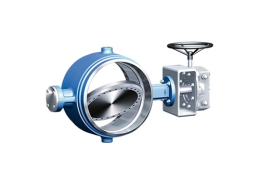
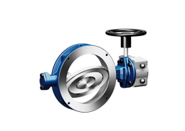
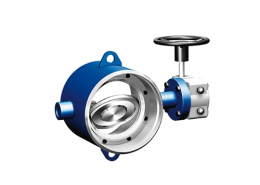
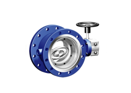
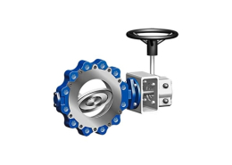
ARI-ZEDOX 122
Double flanged high performance valve – Double offset
ARI ARMATUREN INDONESIA – Steam product solution
- ADCA VPA26/2 Intermittent Blowdown Valve | VALSTEAM DN 20–DN 50
- ARI-ZESA Butterfly valve with elongated eyelets and notch lever
- ARI-GESA Butterfly valve with threaded eyelets – soft sealed
- ARI-ZIVA Z Butterfly valve with elongated eyelets and notch lever
- ARI-ZIVA G Butterfly valve with threaded eyelets and notch lever
- ARI-ZETRIX 016 Double flanged process valve
- ARI-ZETRIX 018 Threaded flange process valve
- ARI-ZETRIX 019 Butt weld ends process valve with metallic sealing
- ARI-ZEDOX 120 Wafer type high performance valve
- ARI-ZEDOX 121 Butt weld ended high performance valve
- ARI-ZEDOX 122 Double flanged high performance valve
- ARI-ZEDOX 123 Thread Connection high performance valve