")
Description
| eClass-No.: | 37012290 |
| Application: | Industrial heating and ventilation systems, residential applications, marked-warehouses, ship building, cooling systems, etc. |
| Medium: | Fluids, air and steam |
Technical data
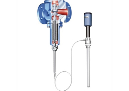
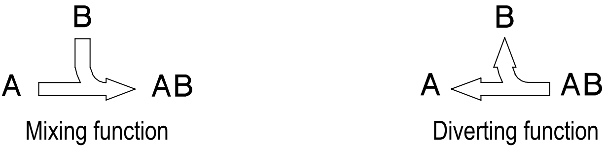
Thermal-mixing/diverting valve – 3way with flanges
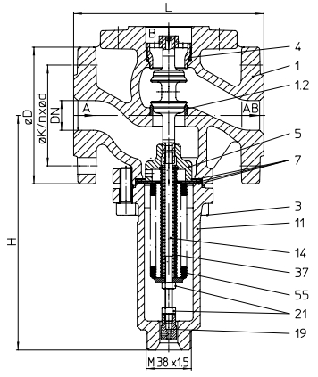
Fig. …773 max. 150°C
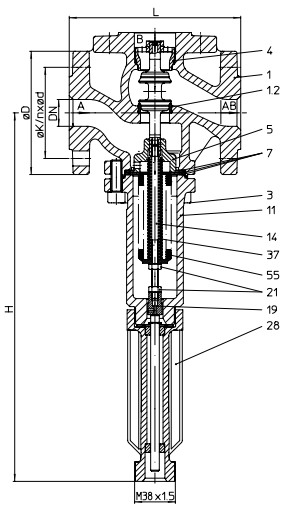
Fig. …774 with cooling spacer max. 300°C
| Figure | Nominal pressure | Material | Nominal diameter |
| 12.773 / 12.774 | PN16 | EN-JL1040 | DN15-100 |
| 22.773 / 22.774 | PN16 | EN-JS1049 | DN15-100 |
| 23.773 / 23.774 | PN25 | EN-JS1049 | DN15-100 |
| 35.773 / 35.774 | PN40 | 1.0619+N | DN15-100 |
| 55.773 / 55.774 | PN40 | 1.4408 | DN15-100 |
| Figure | Nominal pressure | Material | Nominal diameter |
| 12.773….1..1 12.774….1..1 | PN16 | EN-JL1040 | DN15-50 |
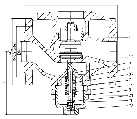
Fig. 12.773….1..1 max. 130°C
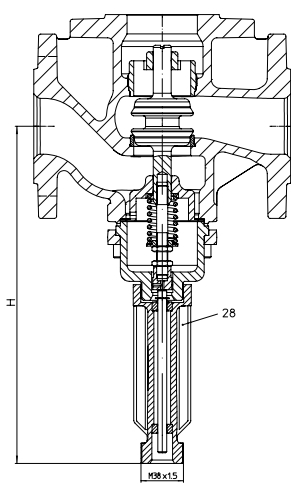
Fig. 12.774….1..1 with cooling spacer max. 250°C
| DN | 15 | 20 | 25 | 32 | 40 | 50 | 65 | 80 | 100 |
| Face-to-face dimension FTF series 1 according to DIN EN 558 Standard-flange dimensions refer to page 15. | ||||||||||
| L | (mm) | 130 | 150 | 160 | 180 | 200 | 230 | 290 | 310 | 350 |
| Dimensions | |||||||||||
| Fig. 773 | H | (mm) | 195 | 195 | 200 | 225 | 245 | 280 | 300 | 365 | 385 |
| Fig. 774 | H | (mm) | 340 | 340 | 345 | 370 | 390 | 425 | 445 | 510 | 530 |
| Fig. 773….1..1 (LC) | H | (mm) | 125 | 125 | 130 | 155 | 160 | 160 | — | — | — |
| Fig. 774….1..1 (LC) | H | (mm) | 270 | 270 | 275 | 300 | 305 | 305 | — | — | — |
| Weights | ||||||||||
| Fig. 773 | (kg) | 4,4 | 5,8 | 7,6 | 9,9 | 14,5 | 16,5 | 25 | 31 | 38 |
| Fig. 774 | (kg) | 5,4 | 6,8 | 8,6 | 10,9 | 15,5 | 17,5 | 26 | 32 | 39 |
| Fig. 773….1..1 (LC) | (kg) | 3,5 | 5 | 6,5 | 8,5 | 12,5 | 14 | — | — | — |
| Fig. 774….1..1 (LC) | (kg) | 4,5 | 6 | 7,5 | 9,5 | 13,5 | 15 | — | — | — |
| Kvs-value | |||||||||||
| Standard | Kvs-value | (m3/h) | 4,0 | 6,3 | 10,0 | 16,0 | 22,0 | 32,0 | 50,0 | 70,0 | 80,0 |
| Travel | (mm) | 7,5 | 7,5 | 8 | 9,5 | 9,5 | 11,5 | 14 | 15 | 15 | |
| Reduced | Kvs-value | (m3/h) | 1,0 | — | — | — | — | — | — | — | — |
| Travel | (mm) | 5 | — | — | — | — | — | — | — | — | |
| Max. differential pressure drop Δp | ||||||||||||
| Fig. 773 Fig. 774 | Mixing function | pB > pA (Δp = pB – pAB) | (bar) | 12 | 16 | 16 | 16 | 12 | 9 | 9 | 9 | 9 |
|
pA > pB (Δp = pA – pAB) |
(bar) | 12 | 4 | 4 | 4 | 4 | 4 | 4 | 4 | 4 | ||
| Diverting function |
pAB > pB pAB > pA |
(bar) | 12 | 4 | 4 | 4 | 3 | 1,5 | 0,7 | 0,25 | 0,15 | |
| Fig. 773….1..1 (LC) Fig. 774….1..1 (LC) | Mixing function | (bar) | 3 | 3 | 2,5 | 1,5 | 1 | 0,5 | — | — | — | |
| Diverting function | (bar) | 3 | 3 | 2,5 | 1,5 | 1 | 0,5 | — | — | — | ||
| Pressure balancing of the actuator needed at P1 > max. differential pressure drop Δp (out of table). For pressure balancing use manual control device (Type 9900390011). | ||||||||||||
| Parts | ||||||
| Pos. | Sp.p. | Description | Fig. 12.773 Fig. 12.774 | Fig. 22./23.773 Fig. 22./23.774 | Fig. 35.773 Fig. 35.774 | Fig. 55.773 Fig. 55.774 |
| 1 | Body | EN-JL1040, EN-GJL-250 | EN-JS1049,
EN-GJS-400-18U-LT |
GP240GH+N, 1.0619+N | GX5CrNiMo19-11-2, 1.4408 | |
| 1.2 | Seat | X20Cr13+QT, 1.4021+QT | X6CrNiMoTi17-12-2, 1.4571 | |||
| 3 | Cheese head screw | A2-70 | ||||
| 4 | x | Plug guiding | X20Cr13+QT, 1.4021+QT | X6CrNiTi18-10, 1.4541 | ||
| 5 | Giude bushing | X20Cr13+QT, 1.4021+QT | X6CrNiTi18-10, 1.4541 | |||
| 7 | x | Gasket | Graphite | |||
| 11 | Bonnet | EN-JS1049, EN-GJS-400-18U-LT | GX5CrNiMo19-11-2, 1.4408 | |||
| 14 | x | Spindle unit | X20Cr13+QT, 1.4021+QT / X6CrNiTi18-10, 1.4541 | X6CrNiTi18-10, 1.4541 | ||
| 19 | Bearing cover | X6CrNiTi18-10, 1.4541 | ||||
| 21 | Hexagon nut | A2-70 | ||||
| 28 | Cooling spacer | EN-JS1049, EN-GJS-400-18U-LT | X6CrNiTi18-10, 1.4541 | |||
| 37 | x | Compression spring | X12CrNi17-7, 1.4310 | |||
| 55 | x | Balanced bellow | X6CrNiTi18-10, 1.4541 | |||
| └ Spare parts | ||||||
Information / restriction of technical rules need to be observed!
Operating and installation instructions can be downloaded at www.ari-armaturen.com. ARI-Valves of EN-JL1040 are not allowed to be operated in systems acc. to TRD 110.
A production permission acc. to TRB 801 No. 45 is available (acc. to TRB 801 No. 45 EN-JL1040 is not allowed.) The engineer, designing a system or a plant, is responsible for the selection of the correct valve.
Resistance and fitness must be verified (contact manufacturer for information, refer to Product overview and Resistance list).
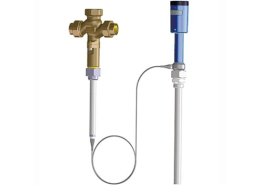
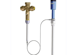
ARI-TEMPTROL® 773/774
Thermal-mixing/diverting valve – 3way with flanges without cooling spacer (max. 150°C)
ARI ARMATUREN – Steam product solutions
- ARI-TEMPTROL® 771/772 Thermal-closing valve
- ARI-TEMPTROL® 771 LCG Thermal-closing valve ARI Armaturen
- ARI-TEMPTROL® 775 Thermal-opening valve ARI Armaturen
- ARI-TEMPTROL® 775 LCG Thermal-opening valve
- ARI-TEMPTROL® 773/774 Thermal-mixing/diverting valve
- ARI-TEMPTROL® 773 LCG Thermal-mixing/diverting valve