Description
| eClass-No.: | 37010905 |
| Application: | Chemical Industry, processing industry, plant manufacturing |
| Medium: | Steam, aggressive gases, vapours and liquids |
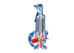
Technical data ARI-SAFE-TC 941 - 942 - 943

| Parts | ||||
| Pos. | Sp.p. | Description | Fig. 25.941/942/943 | Fig. 55.941/943 |
| 1 | Body | EN-GJS-400-18U-LT, EN-JS1049 | GX5CrNiMo19-11-2, 1.4408 | |
| 2 | Screwed seat | X6CrNiMoTi17-12-2, 1.4571 | ||
| 4 | Spindle guide | X20Cr13+QT, 1.4021+QT | X6CrNiMoTi17-12-2, 1.4571 | |
| 7 | x | Gasket | Pure graphite (CrNi laminated with graphite) | |
| 11 | Bonnet, closed | EN-GJS-400-18U-LT, EN-JS1049 | GX5CrNiMo19-11-2, 1.4408 | |
| 12 | Disc | X39CrMo17-1+QT, 1.4122+QT | X6CrNiMoTi17-12-2, 1.4571 | |
| 14 | x | Spindle | X20Cr13+QT, 1.4021+QT | X6CrNiMoTi17-12-2, 1.4571 |
| 17 | Adjusting screw | X20Cr13+QT, 1.4021+QT | X2CrNiMo17-12-2, 1.4404 | |
| 27 | x | Sealing ring | CuFA | X6CrNiMoTi17-12-2, 1.4571 |
| 28 | Cap, closed | EN-GJS-400-18U-LT, EN-JS1049 | GX5CrNiMo19-11-2, 1.4408 | |
| 35 | Lift fork | EN-GJS-400-15, EN-JS1030 | GX5CrNiMo19-11-2, 1.4408 | |
| 36 | Lever, closed | EN-GJS-400-18U-LT, EN-JS1049 | GX5CrNiMo19-11-2, 1.4408 | |
| 37 | x | Spring | FDSiCr / 51CrV4, 1.8159 | X10CrNi18-8, 1.4310 |
| 41 | Lever, open | EN-GJS-400-18U-LT, EN-JS1049 | — | |
| 43 | Bellows (optional) | EPDM 70 Shore A | ||
| 55 | Bellows unit (optional) | X6CrNiMoTi17-12-2, 1.4571 | ||
| 61 | Coupling | X6CrNiMoTi17-12-2, 1.4571 | ||
| 70 | Balanced piston (optional) | X6CrNiMoTi17-12-2, 1.4571 | ||
| └ Spare parts | ||||
| DN | 15 | 20 | 25 |
| Spring ranges: Standard design | ||||
| (barg) | 0,3 – 0,6 | 0,3 – 0,48 | 0,2 – 0,4 | |
| (barg) | > 0,6 – 0,9 | > 0,48 – 0,68 | > 0,4 – 0,88 | |
| (barg) | > 0,9 – 1,35 | > 0,68 – 1,35 | > 0,88 – 1,5 | |
| (barg) | > 1,35 – 2,2 | > 1,35 – 2,1 | > 1,5 – 2,1 | |
| (barg) | > 2,2 – 3,3 | > 2,1 – 3 | > 2,1 – 2,6 | |
| (barg) | > 3,3 – 4,5 | > 3 – 4 | > 2,6 – 3,2 | |
| (barg) | > 4,5 – 5,5 | > 4 – 5,5 | > 3,2 – 4,2 | |
| (barg) | > 5,5 – 6,7 | > 5,5 – 7,7 | > 4,2 – 6,2 | |
| (barg) | > 6,7 – 8,2 | > 7,7 – 11,4 | > 6,2 – 8 | |
| (barg) | > 8,2 – 11 | > 11,4 – 15 | > 8 – 10 | |
| (barg) | > 11 – 13 | > 15 – 20 | > 10 – 15,5 | |
| (barg) | > 13 – 18,5 | > 20 – 28 | > 15,5 – 18 | |
| (barg) | > 18,5 – 32,4 | > 28 – 35 | > 18 – 29,9 | |
| (barg) | > 32,4 – 40 | > 35 – 40 | > 30 – 40 | |
| Spring ranges: Bellows design (optional) | ||||
| (barg) | 5,7 – 6,5 | 4 – 5,7 | 4 – 5,4 | |
| (barg) | > 6,5 – 8 | > 5,7 – 7 | > 5,4 – 6,4 | |
| (barg) | > 8 – 9,3 | > 7 – 9,9 | > 6,4 – 7,4 | |
| (barg) | > 9,3 – 11 | > 9,9 – 14 | > 7,4 – 8,4 | |
| (barg) | > 11 – 15 | > 14 – 21 | > 8,4 – 10,4 | |
| (barg) | > 15 – 19 | > 21 – 28,9 | > 10,4 – 13,4 | |
| (barg) | > 19 – 29 | > 29,9 – 40 | > 13,4 – 16,4 | |
| (barg) | > 29 – 40 | > 16,4 – 20,4 | ||
| (barg) | > 20,4 – 28 | |||
Information / restriction of technical rules need to be observed! A production permission acc. to TRB 801 No. 45 is available.
The engineer, designing a system or a plant, is responsible for the selection of the correct valve.
Resistance and fitness must be verified (contact manufacturer for information, refer to Product overview and Resistance list).
| DN | 15 | 20 | 25 |
| Dimensions | ||||
| G | (inch) | 1/2″ x 3/4″ | 3/4″ x 1″ | 1″ x 1 1/4″ |
| d0 | (mm) | 12 | 15 | 18 |
| A0 | (mm2) | 113 | 177 | 254 |
| GE | (inch) | 1/2″ | 3/4″ | 1″ |
| GA | (inch) | 3/4″ | 1″ | 1 1/4″ |
| b | (mm) | 15 | 16 | 18 |
| l | (mm) | 50 | 50 | 50 |
| l1 | (mm) | 53 | 55 | 58 |
| H | (mm) | 260 | 260 | 260 |
| H (Bellows design) | (mm) | 295 | 295 | 300 |
| X | (mm) | 120 | 120 | 120 |
| C | (mm) | 69 | 69 | 69 |
| Weights | ||||
| standard | (kg) | 3,5 | 3,5 | 3,8 |
| optional: Bellows design | (kg) | 4,4 | 4,4 | 4,7 |
| Pressure-temperature-ratings | Intermediate values for max. permissible operational pressures can be determined by linear interpolation of the given temperature / pressure chart. |
| acc. to DIN EN 1092-2 | -60°C to <-10°C | -10°C to 120°C | 150°C | 200°C | 250°C | 300°C | 350°C | 400°C | 450°C | ||
| EN-JS1049 | PN40 | (bar) | on request | 40 | 38,8 | 36,8 | 34,8 | 32 | 28 | — | — |
| acc. to DIN EN 1092-1 | -60°C to <-10°C | -10°C to 100°C | 150°C | 200°C | 250°C | 300°C | 350°C | 400°C | 450°C | ||
| 1.4408 | PN40 | (bar) | 40 | 40 | 36,3 | 33,7 | 31,8 | 29,7 | 28,5 | 27,4 | — |
| Certified coefficient of discharge Kdr (Values for D/G variable: < 3,5 bar) | |||
| DN | 15 | 20 | 25 |
| TÜV · SV · . . -995 · D/G | 0,64 | 0,60 | 0,75 |
| TÜV · SV · . . -995 · F | 0,45 | 0,42 | 0,53 |
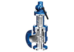
Technical data ARI-SAFE-TC 945 - 946

| Figure | Nominal pressure | Material | Nominal diameter (inlet) | Temperature range | Thread |
| 25.945 | PN40 | EN-JS1049 | DN15 – 25 | -10°C to +120°C | DIN ISO 228 Part 1 |
| 25.946 | PN40 | EN-JS1049 | DN15 – 25 | -10°C to +120°C | DIN ISO 228 Part 1 |
| Fig. 945 Fig. 946 | |||||
| Construction | ||
| Standard safety valve, spring loaded, direct loaded disc with EPDM insert, EPDM-bellows, closed spring bonnet with control hole, open lifting device, stainless steel seat and spindle | Standard safety valve, spring-/weight loaded, direct loaded with EPDM-bellows, closed bonnet with control hole, open lifting device, stainless steel seat and spindle | |
| Application | ||
| acc. to DIN EN 12828 Heating systems in buildings | For low pressure steamgenerators up to 1 bar,
acc. to DIN 4750 and DIN EN 12828 Heating systems in buildings |
|
| Requirement | ||
| acc. to DIN EN ISO 4126-1 / TRD 721 Part 6 | acc. to DIN EN ISO 4126-1 / TRD 721 Part 5 | |
| Type-test approval | ||
| Spring loaded: TÜV · SV · . . -997 · D/G/H | Low pressure steam – safety valve: TÜV · SV · . . -997 · D | |
| Sizing | ||
| Acc. to TRD 721 Part 6.2.5, refer to “Capacity”. | refer to “Capacity” | |
| Order data: | ||
| ARI-SAFE-TC – spring loaded, Figure ….., DN … / …,
PN .. / .., Material …….., Set pressure …. barg |
ARI-SAFE-TC – Low pressure steam – safety valve, Figure …, DN … / …, PN .. / …, Material …, Set pressure …barg | |
| Parts | |||
| Pos. | Sp.p. | Description | Fig. 25.945/946 |
| 1 | Body | EN-GJS-400-18U-LT, EN-JS1049 | |
| 2 | Screwed seat | X6CrNiMoTi17-12-2, 1.4571 | |
| 4 | Spindle guide | X20Cr13+QT, 1.4021+QT | |
| 7 | x | Gasket | Pure graphite (CrNi laminated with graphite) |
| 11 | Bonnet, closed | EN-GJS-400-18U-LT, EN-JS1049 | |
| 12 | x | Disc | X6CrNiMoTi17-12-2, 1.4571 |
| 14 | x | Spindle | X20Cr13+QT, 1.4021+QT |
| 17 | Adjusting screw | X20Cr13+QT, 1.4021+QT | |
| 29 | Cap, open | EN-GJS-400-18U-LT, EN-JS1049 | |
| 37 | x | Spring | FDSiCr |
| 41 | Lever, open | EN-GJS-400-18U-LT, EN-JS1049 | |
| 43 | Bellows (optional) | EPDM 70 Shore A | |
| 61 | Coupling | X6CrNiMoTi17-12-2, 1.4571 | |
| └ Spare parts | |||
| DN (inlet) | 15 | 20 | 25 |
| Spring ranges: Standard design | ||||
| (barü) | 0,3 – 0,6 | 0,3 – 0,5 | 0,2 – 0,4 | |
| (barü) | > 0,6 – 0,9 | > 0,5 – 0,7 | > 0,4 – 0,9 | |
| (barü) | > 0,9 – 1 | > 0,7 – 1 | > 0,9 – 1 | |
| (barü) | > 1 – 1,35 | > 1 – 1,35 | > 1 – 1,5 | |
| (barü) | > 1,35 – 2,2 | > 1,35 – 2,1 | > 1,5 – 2,1 | |
| (barü) | > 2,2 – 3,3 | > 2,1 – 3 | > 2,1 – 2,6 | |
| (barü) | > 3,3 – 4,5 | > 3 – 4 | > 2,6 – 3,2 | |
| (barü) | > 4,5 – 5,5 | > 4 – 5,5 | > 3,2 – 4,2 | |
| (barü) | > 5,5 – 6,7 | > 5,5 – 7,7 | > 4,2 – 6,2 | |
| (barü) | > 6,7 – 8,2 | > 7,7 – 11,5 | > 6,2 – 8 | |
| (barü) | > 8,2 – 11 | > 11,5 – 15 | > 8 – 10 | |
| (barü) | > 11 – 13 | > 15 – 16 | > 10 – 15,5 | |
| (barü) | > 13 – 16 | > 15,5 – 16 |
Information / restriction of technical rules need to be observed!
The engineer, designing a system or a plant, is responsible for the selection of the correct valve.
Resistance and fitness must be verified (contact manufacturer for information, refer to Product overview and Resistance list)
| DN (inlet) | 15 | 20 | 25 |
| Dimensions | |||||
| G | (inch) | 1/2″ x 3/4″ | 3/4″ x 1″ | 1″ x 1 1/4″ | 1″ x 1 1/2″ |
| d0 | (mm) | 12 | 15 | 18 | 18 |
| A0 | (mm2) | 113 | 177 | 254 | 254 |
| GE | (inch) | 1/2″ | 3/4″ | 1″ | 1″ |
| GA | (inch) | 3/4″ | 1″ | 1 1/4″ | 1 1/2″ |
| b | (mm) | 15 | 16 | 18 | 18 |
| l | (mm) | 50 | 50 | 50 | 50 |
| l1 | (mm) | 53 | 55 | 58 | 58 |
| H | (mm) | 260 | 260 | 260 | 260 |
| X | (mm) | 120 | 120 | 120 | 120 |
| Weights | |||||
| standard | (kg) | 3,5 | 3,5 | 3,8 | 3,8 |
| Pressure-temperature-ratings | Intermediate values for max. permissible operational pressures can be determined by linear interpolation of the given temperature / pressure chart. |
| acc. to DIN EN 1092-2 | -60°C to <-10°C* | -10°C to 120°C | 150°C | 200°C | 250°C | 300°C | 350°C | 400°C | 450°C | ||
| EN-JS1049 | PN40 | (bar) | on request | 40 | 38,8 | 36,8 | 34,8 | 32 | 28 | — | — |
| Certified coefficient of discharge Kdr (Values for D/G/H variable: < 3,5 bar) | ||||
| DN | 15 | 20 | 25 | |
| TÜV · SV · . . – 997 · D/G/H | (bar) | 0,64 | 0,60 | 0,75 |
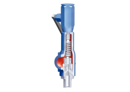
ARI-SAFE TC
Full lift/Standard safety valve with thread connection – acc. to VdTÜV sheet 100, AD2000-A2 and EN ISO 4126-1
ARI ARMATUREN – Steam product solution
- ARI-SAFE Full lift/Standard safety valve with flanges
- ARI-SAFE-P Standard safety valve with flanges
- ARI-SAFE-P 920 Standard safety valve with flanges
- ARI-SAFE-TC Full lift/Standard safety valve
- ARI-SAFE-TCP closed bonnet – closed lifting device
- ARI-SAFE TCS for horizontal application ARI Armaturen
- ARI-SAFE-SN ANSI ANSI-Full lift/Standard safety valve
- ARI-REYCO R Series ANSI-Full Nozzle -Safety Relief Valve
- ARI-REYCO RL Series ANSI-Full Nozzle-Safety Relief Valve